
Saturday, 26 November 2011
Computer hardwere Notes
Do you like this story?
VARIOUS PARTS OF COMPUTER
- MOTHER BOARD
- CPU
- CABINET
- SMPS
- CPU HEAT SINK &FAN
- RAM
- HDD
- FDD
- CDR
- CDRW
- AGP CARD
- LAN CARD
- VARIOU SCREWS
1) MOTHER BOARD:-
It is a main board as usually called as system board, planer board. It holds the majority of a computer’s processing power. It is like chassis of a car. Where every thing is connected.
Is thin flat piece of circuit board which contains the CPU, clock ,timing circuits, memory slots, BIOS, PCI slots, AGP slot ,North bridge, South bridge ,various clip sets along with I/O Slots.
It has chips and other components soldered and connected by tiny copper, wires or tracks look like networks streets across acity.these tracks are the connections that enable the Chips resistors, capacitors to talk to another.

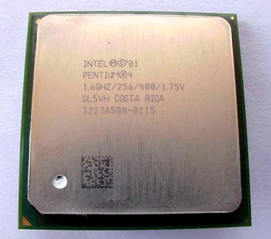
2) C P U:-
It is the brain of the computer. It is the main chip does all the processing, communicates with the input out put devices and performs the task given by the user
It‘s computers the various models. Starting from 8088 to present P1V, 4.0GHz (4.77 MHz to 5GHz) liker various frequencies.
The CPU manufactures are Intel, Cyrix and, IBM, Nexgen,etc..
It’s related with different parameter like speed, efficiency, frequency, word size, address bus, super scaller execution, and cache memory.
3)CABINET:-
The cabinet is the other casing of aP.C . it’s available either as desktop or tower type
It forms the mechanical foundation of every Pc and other sub assemblies are fixed securely to it
It’s typically offered a room
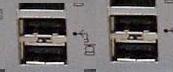
SMPS:-
The power supply is the silver box that’s usually located at the near the side of the cabinet
- It capacity of power supply is mention in watts. It’s available different voltage like 200w to 315w
- It indicates one fan, and two power sockets. These are one A/C input another A/C output
- Ac power supply is applied through ac line cable at the A/C input, and then the power supply produces as a series of DC out put that power cabinet to motherboard and or other drives.

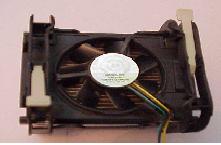
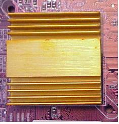
CPU HEAT SINK & FAN
It’s a alumni coated sink with fan. It’s using for processor cooling. It causes of the more clock cycles in given a period the more current is required and then more heat is generated in CPU.
- In that time CPU over clocking that is usually they want to cooling
- When over clocked a CPU, it can easily over heat and crash of permanent damage .that’s why to making accommodation for better cooling with heat sink & fan
- When installing the cooling unit, be sure that it fits on the CPU tightly with out any air gaps, and use a thin layer of thermal grease (Heat sink compound) between the CPU and heat sink.
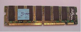
RAM:-
It is for a computer to work the CPU must take program instructions and exchange data directly with memory as a consequence memory must keep pace with the CPU or make the CPU wait for it to catch up.
- Now a day’s processor is very fast, memory architectures are being replaced specialized memory devices that have been tailored to serve specific functions in the PC.
- Ram consists of some chips and small circuit board. It’s measured in Bytes
- Ram’s are available different types. They are
- D RAM
- SD RAM
- RD RAM
- DD RAM
- It uses magnetic storage technology to store data.
- Olden day’s it is heavy and low capacity like 10MB 20MB
- Now a day’s it is replaced by lightly and fast like 100GB
- Hard drive has provided the reliable and quite storage mechanisms.
- It is measured in bytes.
- Hard drives are standard equipment on all PC’s and are preferred boot device for quick loading of even the largest operating systems.
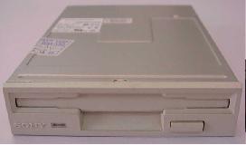
- In spite of it’s limited storage capacity the floppy drive in the traditional pc drive, which is universally accepted in virtually every pc manufactured.
- Originally developed for the music industry, as a digital replacement for phonographs, the CD ROM quickly found in modern computers(PC’s).
- One optical disk can store up to 700MB of programs, data, or other media such as audio and video
- CD Rom drives are standard equipment in all modern PC’s
- It is high-density optical storage disk reader
- It is working with laser diodes project light beam toward desired track
- Prism directs reflected light beam pulses to light sensor
- Light sensor circuit generates digital pulse stream
- CD is recording in as spiral pattern as a series of pits and lands pressed in to plastic substrate
- AGP CARD utilize main memory for graphic purpose
- AGP inter face specification uses the 66MHz or higher
- AGP data transfer rate 133MHz, if allowing for real data out put in excess of 500MB/sec
- AGP is physically, logically high speed bus data transfer
- AGP card is not compatible for PCI slot
HDD
It is secondary storage memory and permanent storage memory
It is consisted of mechanics are Frame, Platters, Read Write heads, head actuators,
Spindle motor, media consists of disk heads, sectors, clusters and cylinders.

FDD
Floppy disks has available in two sizes 1.1.2MB.2.1.441MB it is appeared first 1BMPC
CDR
It is only for reading drive
It is constructs with frame , front panel , main PC board drive engine, slider assembly , motors, optical device and sled.
CDRW:-
It is read and write device, same as above CDR .
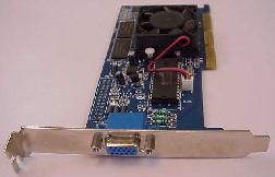
AGPCARD:-
The AGP CARD developed by uses of the variations of the PCI bus slot to provide a high speed data path way between the 3D video card and main memory
LAN CARD
It is a PCI card; it is used for counting one computer to one or above computers.

VARIOUS PARTS OF THE P 4-MOTHER BOARD
P4 motherboard is of the ATX Type motherboard.
Here all I/O Ports are constructed in a single I/O panel. At rear side of the motherboard. This type of board’s use a 20-pin style power supply connector, from the Power Suply.The CPU is located clear and away from all expansion bus slots eliminating interface with full slot expansion cards.
P4 motherboard contains the following parts.
1) Socket 478
2) North Bridge
3) Southbridge
4) RAM slots
5) IDE slots (Integrated Device Electronics)
6) CMOS battery (Complementary Metal Oxide Semiconductor)
7) BIOS (Basic Input Output System)
8)PCI slot (Peripheral Components Interface)
9)AGP card (Accelerated Graphics Port
10)ATX Power connector (Advanced Technology xtremed)
11) 12.V 4pinPower Connector
12) FDD connector
13) System Fan connector
14) CD in Jack
15) CMOS Jumper
16) I/O Ports (Input-Output connector)
17) Front Panel connectors
P4 motherboard
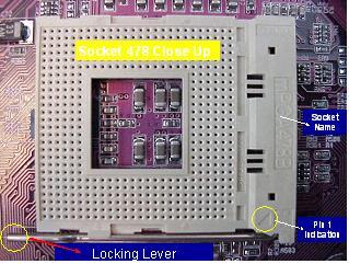
 SOCKET 478:--
When you find Mother board you will probably find it designated socket 478 on which the processor will be placed. This socket 478 only supports P4-pinning processor.
 NORTH BRIDGE:--
It is helpful for the CPU to process the data or functions controllers each and every components through in this bridge. The instruction will pass from socket to Bridge, N-Bridge to RAM slots, and AGP slot
NORTH BRIDGE:--
It is helpful for the CPU to process the data or functions controllers each and every components through in this bridge. The instruction will pass from socket to Bridge, N-Bridge to RAM slots, and AGP slot
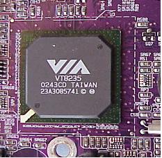
 SOUTH BRIDGE:-
It is also helpful for processor. It is transferring instructions communicate with all I/O ports, FDD port, PCI slots and IDE slots to Socket 478.
 CMOS BATTERY:-
Computer uses 3 volts Lithium Battery. It is supplying power to the CMOS chip(BIOS)
[Complementary Metal Oxide Semiconductor]
RAM SLOTS:-
The individual memory chips soldered by one circuit board that’s called RAM. So removing & replacing that cards, designed RAM slots
i.e SD, DDR
 IDE SLOTS (PRIMORY AND SECONDARY):-
It is a 40 pin connector. These are used for connecting IDE drives (HDD, CDR, CDRW, DVD) in every motherboard will have two ports.
IDE SLOTS (PRIMORY AND SECONDARY):-
It is a 40 pin connector. These are used for connecting IDE drives (HDD, CDR, CDRW, DVD) in every motherboard will have two ports.
1) Primary
2) Secondary
In one port can connect one bus cable, with one cable can connect two drives, so in one board had two slots, in one system can connect four drives. It connect in primary these primary master, primary slave at same in secondary.
 BIOS:-
The BIOS is a 128/256 KB of EP ROM. That contains the Basic Input Out put System code.
The CPU to handle all I/O confits and data transfers uses this code. It is input like a remote controller.
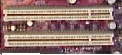
 PCI SLOT’S:-
It is by passes the standard I/O bus; it helps the system bus to increase bus clock speed & CPU’s data path. Its available 32 and 64 bit. In this bus interface the the PCI cards such as SOUND, VGA CARD, TV TUNER CARDS.66MHz speed. it is designed for installation of interfacing cards only.
 AGP SLOT:-
It’s passes high-speed graphic display adapter bus slot. Its 133MHz speed. It is designed for only installation of AGP CARD.
 ATX MAIN POWER CONNECTOR:-
It is a 20-pin connector. It is discharge DC voltages to motherboard. These 20 pins are (+ve to –ve)
1 2 3 4 5 6 7 8 9 10
11 12 13 14 15 16 17 18 19 20
First two pins are +ve 3rd pin –ve, 456 pins a gnd, 7th pin is –ve and 8th pin is ground, 9th 10th are –ve and are –ve, 20 pins +ve
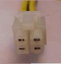
 12 VOLTS 4PIN CONNECTOR:-
It is a 4 pin connector, It placed on the board at nearest socket 478. It is a reverse power connector.
 FDD CONNECTOR:-
It is a 36 pin connector, used for connecting floppy drive in one system can connect the two FDD drives. That drive letters indicates always A, B.
 SYSTEM FAN CONNECTOR:-
It is a 3pin connector used for connecting the CPU fan or system fan. Pin 1 is ground; Pin 2 is +12v and 3is a fan sense line which can monitor the management.
With out the help of processor directly we can use the maniplate CD Rom Data. In this cable having a analog and digital connectors. One end is connect on mother board in CD in Jack other end is connect to CD drive

This jumper can used clear the CMOS settings, passwords. This jumper can be used to prevent access to the CMOS setup routine
 FRONT PANEL HEADER:-
The group of connectors used to connect front panel switches and indicators, such as the Speaker, Reset, Power LED, HDD LED and Power on switch
 I/O PANEL:-
These are called a back panel. These are the group of I/O connectors that preside on the rear side. These include
a) PS2 ports like key board, mouse b) serial ports c) parallel port or printer port
d) Usb ports e)AGP/VGA port f)LAN port g) Game or MIDI(MUSICAL INSTUMENT DIGITAL INTERFACE)ports and h)Sound connections
 PS2 PORTS:-There are 6 pin connectors , used for connecting keyboard, mouse
- Installation of Mother Board:- Insert the Mother Board vertically & ensure that the holes of mother board and I/O shield may consist with the cabinet holes then press the - mother board firmly or tightly on the copper nuts with I/O panel facing back side of cabinet, and fix the screws.
- Installation of CPU:- To insert the processor on socket 478( White rectangle shape) first we have to identify the starting pin from where we have to insert.To identify the starting pin the following are clues.
- SPKR(SPEAKER)
- PWS(POWER SUPPLY ON-OFF SWITCH)
- PLED(POWER LIGHT EMITING DIODE)
- HDD LED(HRD DIDK LED)
- Typical
- Portable
- Compact
- Custom
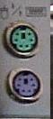
KEY BOARD MOUSE
VOILET GREEN
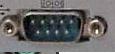
SERIAL PORT:-
It’s a 9 pin D Type Male connector used for connecting the serial mouse and External Modem
 PARALLEL PORT:-
(That can operate in standard mode Enhanced Parallel Port(EPP)mode with BIOS and driver support or high speed Extinction Capabilities Port(ECP) mode)
It is used for connecting to printer. It is 25 pins D Type female connector.
 USB PORTS:-
These are high speed serial bus controllers. Now a days all input and out put devices can connect through these connectors. Such as web cam, keyboard, mouse, pen drive, scanner, printer, cell phone, mp3 players, DVD play units, storage drivers, cd/dvd writers.
 AGP/VGA:-
It is a on board display connector it is a 15 pin D type female connector. It can used for connectible display unit such as monitors, screen projectors.
 LAN PORT:-
It is a communicate on board Ethernet port. It can use for connecting to other computers in LAN.
 GAME/M1D1 PORT:-
It is D type pin female connector It used for connecting to game devices say it can musical instruments.
 SOUND PORTS:-
It is 3 pin (3HOLE) connector. These are 2 out put 1 in put pins. Such as external speaker out , head phone and mic.
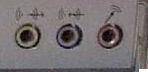 One hole is output speakers
One hole is line sound
One hole is mic connecotor.
One hole is output speakers
One hole is line sound
One hole is mic connecotor.
ASSEMBLING OF A PC
Required parts:
1. Cabinet,
2. Mother Board
3. P4-Processor.
4. RAM
5. S.M.P.S
6. HDD.
7. FDD
8. CD ROM.
9. IDE Cables
10. Screws.
( Monitor, KeyBoard, Mouse)
PROCEDURE
1.Prepare the chasis or cabinet:- Select the holes of cabinet and fix the plastic
locks or copper nuts on the sheet inside the cabinet. Ensure that I/O shield is
suitable for mother board ,I/O panel,compare and fix I/O shield.
a) At upper right corner there will be one arrow head
b) At that symbol one pin will be missed
4. Installation of CPU Heat sink& Fan:- Insert the heat sink and fan first in
correct position on the CPU & soket 478.Tthen lock(press) the four edges of
heat sink, they will lock automatically.Now manually lock two levers in
opposite direction on the heat sink fan for tightness of heat sink.Then
connect the fan cable to 3 pin power connector on the mother board ,which
is placed beside the socket 478 & also there will be written ‘CPU_FAN’.
5. Installation of the RAM:- To observe the RAM slots and RAM cards on
the mother board , while fixing suitable RAM hold the two ends correctly
and press by applying same energy on both ends.If you correctly inserted,
you can here a small click on sound.
6). Installation of SMPS:-Insert the SMPS in cabinet such that,’ in side to back showing the power connections ‘ and fit the screws at the back side of cabinet.
8).Installation of HDD:- Insert the hard disk in inside of cabinet front box, fit the screws. Connect the IDE cable such that long edge must go to mother board IDE connector & short edge must be with drive. To give power supply there is one D-type power connector with 4 wires from SMPS.Insert the connector to hard disk.
Note: Take care while you are inserting power connector the red color of IDE card & red color of power connector shold be sibe by side.
9).Installation of FDD:- Open front side of cabinet FDD cover and insert the FDD from out side to inside , fit the screws. Fit the cable one edge is on mother board FDD connector &, second edge connected to FDD. To give power supply to the drive there is one E-type power connector with 4-wires ,so connect the connector to FDD.
10).Installation of CD-ROM Drive:- Open the front side of cabinet CD-ROM block and insert the CD-ROM from out side to inside, & fix the screws. Connect the IDE cable and D-type power connector(Just like HDD ),CD in jack cable.
11).Installation of LAN Card:- Insert the LAN card in PCI slot correctly,& fix the screw out side showing connector correctly.
12).Connections of Power Cables:- ATX Power supply: - Insert the ATX power connector on motherboard and press it lockly. 4-pin power connector :- Connect the motherboard and install the clipping 12V Power connector at behind of CPU. D-Type Power Connectors: - There are 4 D-type connectors to give power supply to IDE drives. Those are HDD ,CD-ROM,CD-RW DVD R/W . E-Type Power Connectors:- This used only for FDD power supply. Connections of Data Cables:- 80 Pin or 40 Pin IDE Connector connects only IDE Drives, at one edge to IDE drive and second edge will connect to the mother board. 36Pin FDD cable connected to one side a motherboard and second side is Floppy Disk Drive. Front Panels Connections: - It is the most important session .In this session there will be five types of cables.INSALATION OF WINDOWS 98
Objective: - How to install windows 98
Installation:- Before install windows 98 make sure your computer meets the following minimum requirements
Processor: 66 MHz of higher
Ram: 16MB
HDD: 1GB
VGA Monitor
CD -Rom
Mouse
Keyboard
Procedure:-Insert Windows 98 startup disk (Bootable CD or Floppy) in your computer.
The Micro soft Windows Start up menu appears.
Select the Start computer with CD Rom Support.
Press Enter.
A series of scan is performed and then the MS-DOS prompt appears.
At the MS-DOS prompt select the windows 98 directory where available drive.
(CD Win 98 Enter)
Then type the word of setup and press enter. A message informs you that setup is going to perform a check (Scan disk running) Press Enter.
Micro Soft scan disk is checks your had disk for errors.
When scan disk finish Press X button or exit button.
To exit scan disk after that setup initializes Windows 98 setup begins
Select directory screen.
If you want to Windows 98 Installation files in a folder (Directory).
C:\WINDOWS;
Other than click other directory. And type the folder name.
Click Next Button. Setup shows the options screen.
Setup option screen.
You can customize version of Windows by choosing the components that are installed on your hard disk setup options screen asks you to select the type of setup you prefer. You can choose from the Four-setup options.
These are
Choose in this four options typical or custom Press Next button
Windows components screen:-
On this screen you chose whether or not to view a list of installation options.
If you select install the
On this screen you enter a name, work group and description for your computer. If your computer is connected to network this information is identifies your computer to other users.
Click the next button to continue.
ESTABLISHING YOUR LOCATION SCREEN.
On this screen you should probably select the country in which you live your selection here controls the channels available on your channel bar.
Next screen will prompt you to create a startup disk. Click the next button.
Click OK button to create startup disk.
Click the continue button to skip creating startup disk.
Window 98 has now enough information to start copying Windows 98 files your computer.
Click next button to start copying files.
Setup will restart the computer.
After restarting the system you will get windows 98 screen with message getting ready to run windows for the first time]
NEXT SCREEN WILL PROMPT YOU TO TYPE YOUR NAME AND COMPANY NAME.
License agreement screen:-
Next screen will prompt you for license agreement. Select I accept the agreement and click the next button to continue.
KEY- w4cw4—m79g9—297tc—y8t7p—8yd3b
Next screen prompts you enter product key. Type the product key in spaces provided. The product key is located either on the certificate of authentication of back of your windows 98 CD Rom
Click the finish button to continue start windows 98.
Next windows had detected plug and play hard ware peripherals in your computer.
Now during the setting of hard ware the screen will prompt time zone to apply
Select the time zone and click the apply button then click the OK button
Select the time zone GMT+530.
In the progress windows will also make the settings for following options
CONTROL PANEL
PROGRAMS ON START MENU
WINDOWS HELP
MS-DOS POGRAMS
SETTING UP APPLICATIONS
SYSTEM CONFIGIRATION
Now setup will restart the computer and your installation process is completed
Conclusion:-
Thus we have studied the installation of Windows 98

This post was written by: Franklin Manuel
Franklin Manuel is a professional blogger, web designer and front end web developer. Follow him on Twitter
Subscribe to:
Post Comments (Atom)


2 Responses to “Computer hardwere Notes”
7 June 2016 at 20:49
good but convert to pdf and uplode the downlod link ok good night 7036497145....................
4 April 2022 at 20:49
Computer Hardwere Notes ~ Anjis World >>>>> Download Now
>>>>> Download Full
Computer Hardwere Notes ~ Anjis World >>>>> Download LINK
>>>>> Download Now
Computer Hardwere Notes ~ Anjis World >>>>> Download Full
>>>>> Download LINK a7
Post a Comment